I want to wire 2) 8 ohm speakers for both 4 &16 ohms. The "plug and play" jack plate seems the ideal solution, but for the fact that they're out of stock everywhere I've looked (except EBay, where they're over twice the price!).
Could anyone help me out with a wiring diagram? Could be 2 jacks, or a switch, or some combination... TIA!
Switchable cab impedance
Moderator: Dave Mudgett
-
Dave Meis

- Posts: 1143
- Joined: 8 Jan 2015 7:46 pm
- Location: Olympic Peninsula, Washington, USA
- State/Province: Washington
- Country: United States
-
Bill A. Moore

- Posts: 1435
- Joined: 2 Jul 2007 3:17 pm
- Location: Silver City, New Mexico, USA
- State/Province: New Mexico
- Country: United States
-
Dave Meis
- Posts: 1143
- Joined: 8 Jan 2015 7:46 pm
- Location: Olympic Peninsula, Washington, USA
- State/Province: Washington
- Country: United States

-
Douglas Schuch

- Posts: 1503
- Joined: 10 Jun 2011 9:33 am
- Location: Valencia, Philippines
- State/Province: -
- Country: United States
That is certainly a good way to do it that Bill diagrammed. Here is how you could do it with a switch. You need a Double Pole Double Throw (DPDT) On/Off/On switch. This switch will have six pins, in pairs. Throw the switch one way and it connects the middle pair of pins with their respective pins at one end (typically the end opposite of where the switch is, as it’s a lever with a center pivot). Throw the switch the other direction, and it connects the middle pins to the pins at the other end.
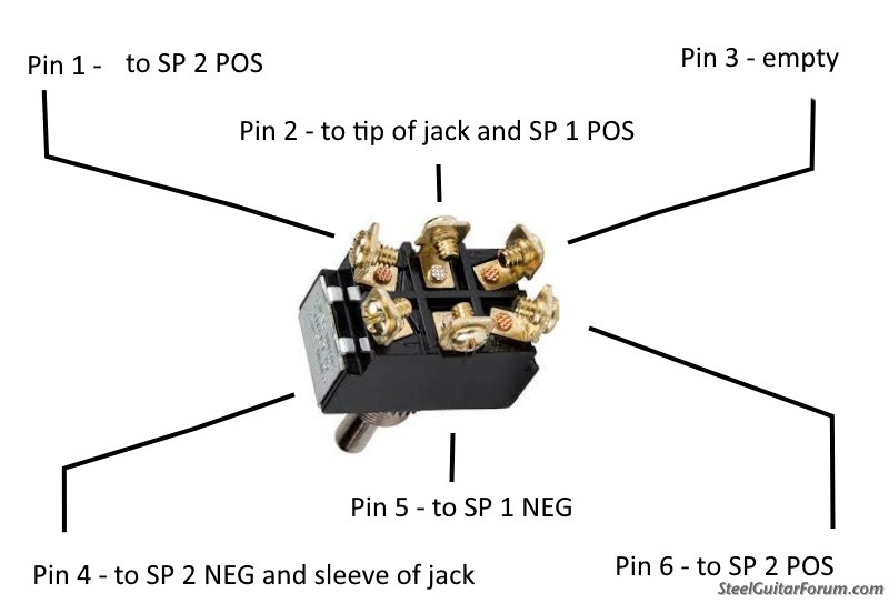
If there is a standard for labeling the pins, I don’t know it, so lets call them this when looking at the back of the switch:
1 2 3
4 5 6
OK. From your input jack, connect the POS (tip) to pin 2. Connect the NEG to pin 4.
From Speaker 1, connect POS to pin 2 or to the tip of the input jack – it’s always POS, so do whichever is easiest. Connect NEG to pin 5.
From Speaker 2, connect POS to pin 6. Connect NEG to 4, or to the sleeve of the input jack – it’s always NEG. Do whichever is easiest.
Last, connect Pin 1 to Speaker 2 POS – you can go to the speaker connection, or just splice it into the wire coming from pin 6, or even to pin 6 along with the other wire.
There are no wires to pin 3.
So, when the toggle switch is to the right, connecting pins 1 to pin 2, and pin 4 to pin 5:
Current flows from the input jack to pin 2, and on to speaker 1. It returns from speaker 1 to pin 5, which is connected to pin 4, which is connected to the sleeve of the input jack.
It also flows from pin 2 to pin 1, which is connected to Speaker 2 Pos. and returns via speaker 2 neg. to sleeve of input jack – speakers are in parallel, so two 8-ohm speakers will equal 4 ohms total.
When the switch is to the left, pin 2 is connected to pin 3, pin 5 is connected to pin 6:
Current flows from the tip of the input jack to speaker 1 Pos (possibly via pin 2). It returns via speaker 1 NEG to pin 5, which is connected to pin 6, which goes to Speaker 2 POS, and returns via Speaker 2 NEG to pin 4, and on to sleeve of input jack – thus the speakers are in Series and two 8-ohm speakers should net at 16 ohm.
Remember – it can damage a tube amp to disconnect a speaker while playing, and switching positions with this switch it passes through “off” – so mute/standby/turn volume down on amps before switching it.
Here is a diagram:
Hopefully someone will review this for typos/brain farts. Always good to check with your multi-meter before powering up!
Bringing steel guitar to the bukid of Negros Oriental!
-
Dave Meis
- Posts: 1143
- Joined: 8 Jan 2015 7:46 pm
- Location: Olympic Peninsula, Washington, USA
- State/Province: Washington
- Country: United States
